Technology Instructions
[ Home ] [ Automotive Tips and Repair Instructions ] [ Computer Tips & Instructions ] [ Household Repairs ] [ Real Estate Professionals ]
NOTICE
These instructions are offered "As Is" and at your own risk. AtTheTipWebs.com,
any of our staff members, affiliates, etc. are not responsible for any problems
that may occur as a result of the use of these instructions, tips, procedures, etc., nor do we offer any support of any
kind by phone, visit, or by e-mail, etc. By using these instructions, tips,
procedures, etc., you accept all
responsibility and liability for the results that occur.
Assembly of the HP DV6000
.jpg)
As with many of these laptop computers I had one with a failed mother board.
I also had one with a failed internal power board adapter. Even though the power
board is separate and has 2 small screws holding it in the lower casing, you
have to remove the entire mother board to replace it. It's a shame they didn't
make that easier.
These instructions will guide you through the process of safely taking the
computer apart so you can replace any and all mother board related parts. If you
are comfortable around working on things, this computer can be torn down and put
back together in less than 1-1/2 hours. When you put the machine back together,
do not over tighten any of the screws, it will likely break the plastic parts.
Tools Required
| Small Cross Tip Screwdriver |
Magnet |
| Small Flat Tip Screwdriver |
Screw Pattern Sheet |
| Medium Size Glasses Repair Flat Tip Screwdriver |
Pressurized Air and/or Brush |
| CMOS Battery CR2032 |
|
DONATION: Please give a donation after you use these instructions. The
recommended amount is $10.
Instructions:
- Put your flat tip screw driver against the magnet for about 5 minutes.
This will magnetize it and help you pull the screws out of the casing.
- Power down the computer if it is on.
- Unplug the computer from the wall.
- Flip the computer over and remove the battery. It has a latch that you
need to slide to one side to cause the batter to raise from the casing.
_small.jpg)
- Remove the DVD player. Remove the 1 screw that holds it in place and pull
it out of the lower casing.
_small.jpg)
_small.jpg)
- Remove the RAM access panel. Loosen the 2 screws and lift the panel from
the base. The screws will stay attached to the panel.
_small.jpg)
- Remove the hard drive access panel. Loosen the 2 screws and slide the
panel towards the edge of the computer. It has 2 tabs that should be shifted
out of the base so you don't break them.
- Remove the hard drive. It has a plastic tab that you can grab and lift the
hard drive out of the base.
_small.jpg)
%20(2)_small.jpg)
- Unplug the 2 wire that connect to the wireless card, 1 black and the other
white. They should be numbered so it's easy to reconnect them.
_small.JPG)
- Remove all of the other screws from the base. There should be 24 remaining
and yes you need to remove them all and place them on the screw sheet.
- Flip the computer over.
- Remove the button board. With the monitor at the back, pry up on the right
side of the board with the medium size glasses flat time screw driver and
work it off from the back edge. Then pull it up across the back.
WARNING: This panel has 3 wire connections connected to it, do not pull it
all the way off before you unplug those wires. One of them simply unplugs,
the other 2 of them has a ribbon retainer that needs to be unlocked before
you pull the ribbon cables loose.
_small.jpg)
_small.JPG)
_small.JPG)
_small.jpg)
- Remove the keyboard. I usually lift up on the center rear edge of it and
work it up and out.
WARNING: The keyboard has a ribbon cable attached to the motherboard. Lift
up the keyboard up from the back and hinge it at the front. Then unlock the
ribbon latch and unplug the ribbon.
_small.jpg)
_small.JPG)
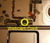
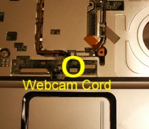
- Remove the monitor. Pull the wires through the motherboard and un-thread
them (you may have to take tape loose as well). Unplug the monitor cable
from the motherboard. Then hold the monitor stable
as you remove the 4 screws that hold the monitor to the base. Once you have
all of the screws out, lift the monitor from the base.
_small.jpg)
_small.JPG)
_small.JPG)
- Unsecure the 2 ribbons that run along the left side of the top of the base
so they will let the top 1/2 off and the ribbons will stay attached to the
motherboard.
_small.jpg)
- Remove the rear edge of the top, it has 1 screw in it if you haven't
already removed it. Then pry it loose from the right side and work your way
across.
_small.jpg)
_small.JPG)
- Take the top 1/2 loose from the lower 1/2. Remove the 3 screws and work
the edges apart, it simply clips together.
_small.jpg)
- Remove the PCMCIA port from the right forward edge. Remove the 4 screws,
unplug it from the motherboard and lift it away from the base.
_small.jpg)
- Remove the 1 screw that holds the mother board to the base and remove the
mother board. It is tucked in the left side pretty good so try not to break
the left side frame when you separate them.
WARNING: The motherboard has 3 wire connections attached to it that you will
have to unplug to get the motherboard removed from the lower base. 2
Connections at the rear edge that go to the power board and 1 connection at
the front where the headphones and mic plug in.
_small.jpg)
_small.jpg)
- Remove the 2 screws that hold the power board to the base and remove it
for replacement.
_small.JPG)
_small.jpg)
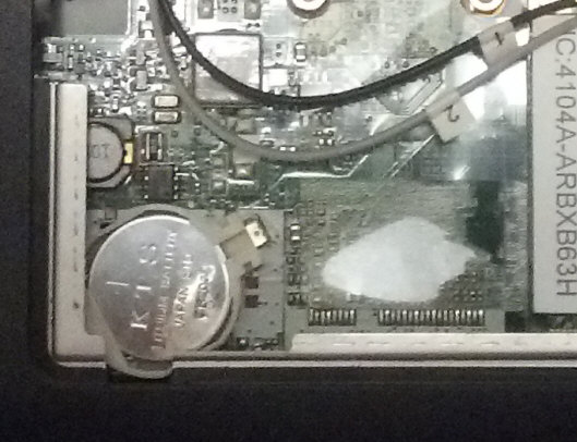
- Clean the fan and heat sink with pressurized air and/or a small brush.
- Replace the CMOS battery.

- To replace the processor, loosen the 4 screws that hold the heat sink to
the motherboard. Remember to use the heat sink grease to the processor top
when installing another processor. After you take the 4 screws loose, lift
the heat sink from the processor, it may be stuck on there. Then take the
flat tip screw and turn it to unlock the processor. Then you can lift the
processor out.
_small.jpg)
- To put the computer back together simply reverse the procedures above.
End of instructions. Please leave a donation. Recommended donation is $10.
I hope these instructions were helpful to you. Please take a minute and leave
me a donation, yes I do need it.
Click Here.
.jpg)
.jpg)
.jpg)
.jpg)
.jpg)
%20(2).jpg)
.JPG)
.jpg)
.JPG)
.JPG)
.jpg)
.jpg)
.JPG)
.jpg)
.JPG)
.JPG)
.jpg)
.jpg)
.JPG)
.jpg)
.jpg)
.jpg)
.jpg)
.JPG)
.jpg)
.jpg)