Lifter Replacement, Volvo 850 / S70 Turbo
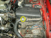
Just finished doing a head gasket job on our S70 GLT. The car had the strangest head gasket leak, one that was new to me.
In the process of doing the head gasket, I realized that I had access
to lifters and some people do have lifter problems that they would like
instructions to fix so here you go. I'm not sure if there are some good
photo instructions out there already, nor have I searched so you may
want to check for yourself. I have found it helpful to look at different
instructions and use the ones that I understand better and that I'm
comfortable using.
My guess is that going right at this job, it would take about 2 hours to
get the cam cover off, 2 hours to clean up the head, then 3 hours to put
everything back together and clean up your work area. So, do allow for 7
hours. If you do the job in less time, please contact me to let me know
so I can update the time schedule. I'm a slow worker. Also, if you find
anything in these instructions are are not proper, please let me know so
I can correct them.
Tools Needed:
| 24 Lifters | Oil, 1 quart |
| Sockets, 1/4" drive: 6mm, 7mm, 7mm deep, 8mm, 8mm deep, 9mm, 10mm, 10mm deep, 12mm | Ratchet Wrenches: 1/4", 3/8", 1/2" |
| Sockets, 3/8" drive: 10mm, 12mm, 13mm, 14mm | Ratchet Extensions: Short 1/4", Long 1/4", Short 3/8", Long 3/8", Long 1/2" |
| Sockets, 1/2" drive: 30mm | Ratchet Adapters: Swivel 1/4", Swivel 3/8" |
| Speed handle | 8" C-clamp |
| Hammer | #7 Allen wrench |
| Torque Bits: T25, T30, T40 | Foot lb torque wrench |
| Flat tip screw driver, medium | Inch lb torque wrench |
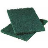
| 4 Squeeze Spring clamps | Plastic scrub pads. |
| Front and rear intake and exhaust cam seals if you want to replace them. Two on each end. I suggest OEM seals. | Timing belt tensioner pin (a small paneling nail should work) |
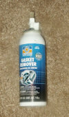
| Anaerobic sealant (gasket maker for putting the top of the head back on. I got mine from NAPA, if you can, get the OEM Volvo stuff) Permatex Anaerobic PN: 51813 | Gasket remover, cleaning solvent |
| Small foam rollers | Small roller pan |
| Brass wire brushes | Plastic scrapers |
| Acetone | White-out paper correction fluid (to mark the cams for timing) |
| Shop towels | Shop paper towels |
| Degreaser cleaner | Throttle body cleaner |
| Lint free rags | Jack stands |
| Jack | Lug nut wrench |
| Drain pan | Magnet |
| Throttle body gasket | Box end wrenches: 17mm, 13mm, 12mm |
| Serpentine belt release tools. I use a special tool that I had made. | Board or other stiff material to lock cams. |
Permatex Anerobic Gasket
Maker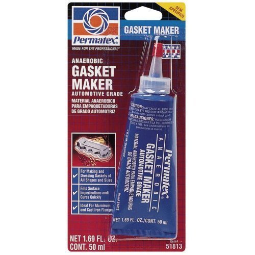 |
Serpentine Belt
Tools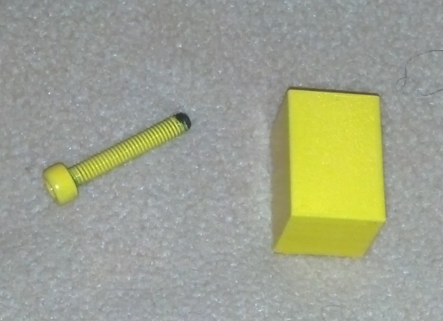 |
Stiff Cardboard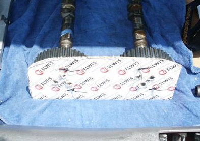 |
Roller For Sealant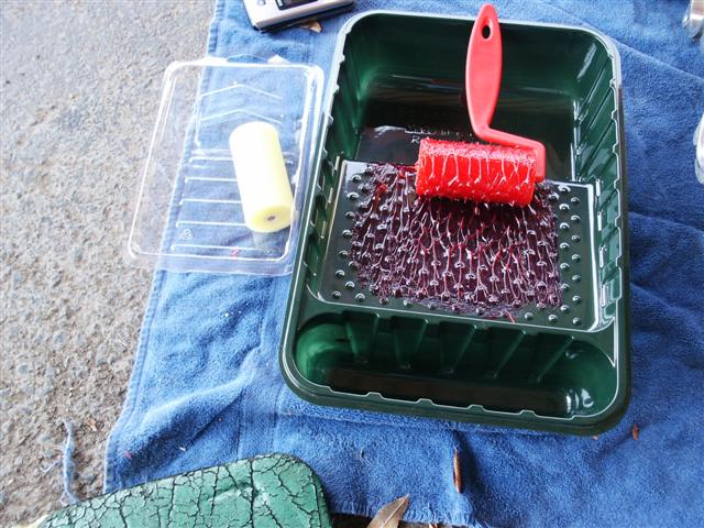 |
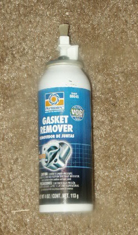
Gasket Remover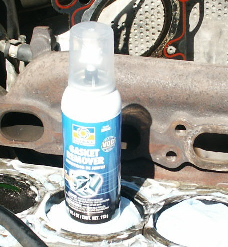 |
Tools Used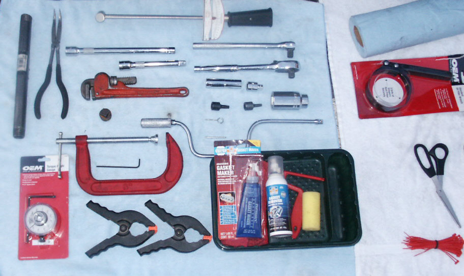 |
Instructions:
-
Park the car on a good level surface.
-
Set the parking brake and/or chalk the rear tires.
-
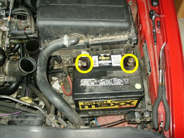
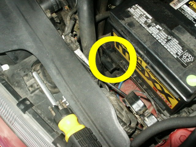
Remove the battery, 10mm. It also has a plastic clip on the tray.

-
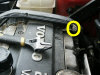
Remove the timing belt cover. One 12mm bolt on the passenger side of the car, hides the cam sprockets and timing belt.
-
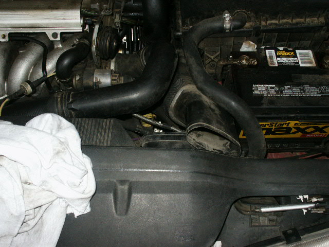
Remove the intake air scoop. Goes from the top of the radiator fan scrod to the lower portion of the air box. Just pulls out.
-
Disconnect the MAF from the intake tubing and the wire plug.
-
Unplug the coil wire.
-
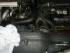
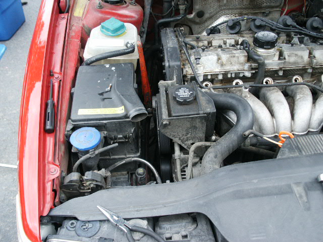
Remove the air box. Disconnect the rubber hose from the front top 7mm, and leave the MAF connected to it. The air box has 2 studs on the bottom of it on the motor side that you lift it up from, the finder side has a prong that goes through a bracket into the finder area. There is also a coil wire clipped to the back side of it and a small wire harness clipped to the back edge closest to the brake fluid reservoir, it lifts out. I did NOT remove the top of the box (exposing the air filter), just remove the entire thing.
-
Remove the throttle body cover if the car still has one. It has 1 T25 screw in it.
-
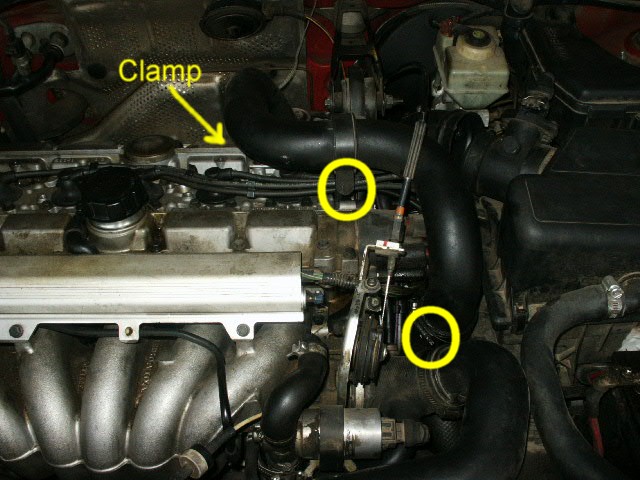
Remove the turbo intake pipe. It has a 10mm bolt dead center, a clamp on the back and a clamp on the front, 7mm I believe.
-
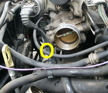
Unplug the throttle body switch.

-
Remove the screw that holds the fuel rail wires to the throttle body cable bracket assembly. 1x T25
-
Remove the fuel rail cover. I just pulls off from the top of it, hinges towards the front of the car. Jerk the top and it will come right off.
-
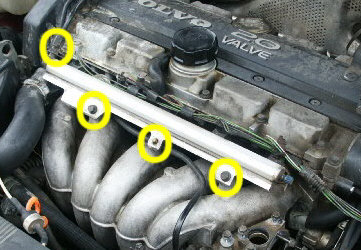
Remove the fuel rail. Undo the 17mm fuel supply line connection, 2x 10mm rail to manifold bolts, unclip the center fuel line and the return line hose that plugs into the manifold. Once you have it loose, swing it towards the throttle cable assembly out of the way.
WARNING: When removing the fuel rail, do you best to pull it straight out and up so you don't damage the fuel injectors. You will likely have to work it out.
-
Remove the spark plug cover from the top of the motor. 6x T30.
-
Unplug the spark plug wires, leaving them plugged into the distributor cap.
-
Remove the bracket for the fuel line near the back side of the timing belt cover. 1x T25
NOTE: Once I disconnected the fuel lines from the bracket, I pushed them around a lot to finish my job. Not a suggestion, just letting you know what I did.
-
Remove the air intake for the ECU box.

-
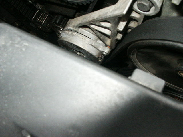
Take the tension off the serpentine belt, pin the idler and remove the belt. It's hard to crank the cam shaft with that belt on the crank.
NOTE: Make sure you make a note as to how the belt came off so you can get it back on easy.
-
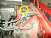
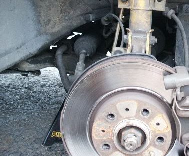
Remove the right front wheel and install a jack stand under the frame.
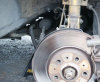
-
Remove the plastic nut that holds the wheel skirt in place over the crank.
-
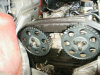
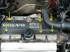
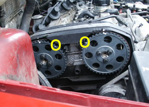
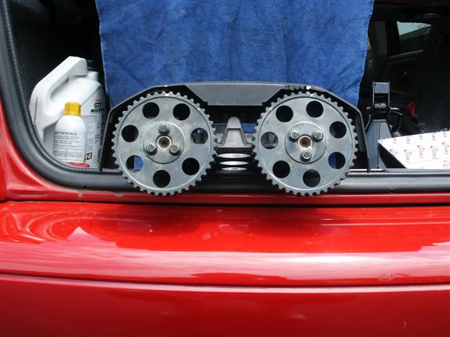
Align the timing marks on the cam sprockets to the top of the timing belt cover by turning the crank clockwise with the 30mm socket.

-
Mark the timing marks on the cam gears. I put 2 marks on each sprocket, one at the mark and another one at the top of the gears onto the cover. I used white-out paint. Quick, easy, dries fast.
-
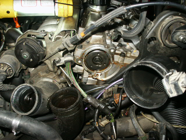
Remove the distributor cap with the wires attached. Mine had flat tip screw driver bolts.

-
Remove the dust cap that was behind the distributor cap.
-
Remove the rotor, #7 Allen (1/8" hex screws). I had to gently tap my Allen wrench in with a hammer.
-
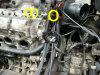
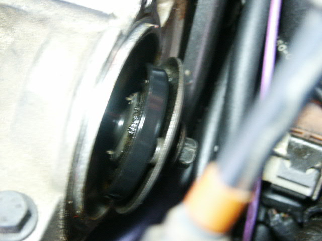
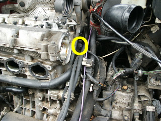
Remove the rear intake cam adapter that was behind the rotor. 10mm bolt.
-
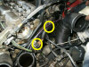
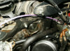
Move the inlet tube out of the way. It has 2 vacuum lines attached to it that I unplugged so I could move the tube around and not totally remove it.
-
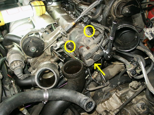
Unplug the cam position sensor. Be gentle, some of those things are fragile.
-
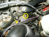
Remove the cam position sensor. 2x T40 bolts. The lower bolt also holds a bracket in place that secures the PCV tubing.
NOTE: These screws are soft so be careful not to strip them.
-
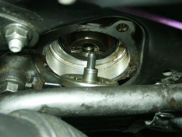
Remove the adapter that was behind the cps. 10mm bolt.

-
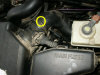
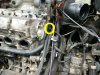
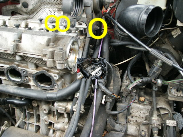
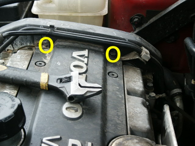
Remove the bracket that holds the turbo inlet tube clamp and secures the top of the head to the upper torque brace. 2x 10mm and the side of it has 1x 13mm nut.
-
Remove the bolt that holds the upper torque brace to the head. 1x 14mm.
-
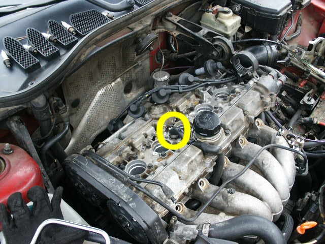
Disconnect the PCV hose on top of the cam cover.

-
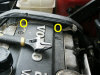
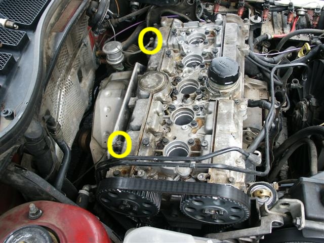
Remove the top of the timing belt cover. 2x 10mm.
-
Remove the 2 rear grounding straps from the head. 2x 10mm.

-
Lock the cams together so they will be in time when you re-install them. Use a stiff piece of cardboard or some other stiff piece of material and make a plate to secure the cams together. I used a very stiff piece of cardboard and zip ties. This kept the cams aligned while out of the motor.


NOTE: This can be done in different ways. Some people lock the cams to the cam cover with a special tool, some make a tool to lock the cams to the cam cover, I just secured them to a board so they would be aligned when I re-installed them. The board also held them straight when I drew down the cam cover during installation. You can look at other instructions to see how they locked the cams to the cam cover.
If you pulled the cams already and want detailed instructions on how I secured them, click here. -
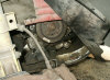
Remove the hydraulic tensioner from the timing belt, 2x 12mm bolts. I removed them from the wheel area. This will make the timing belt loose.
NOTE: After I pulled those bolts, I re-installed the tire (just snugged down the wheel lugs). -
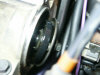
Take the timing belt loose from the cams, only.
NOTE: It is NOT necessary to take the cam sprockets loose from the cams at all. The seals will side over the entire cam length and come off the rear ends when the cams are out of the head/cam cover. -
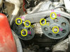
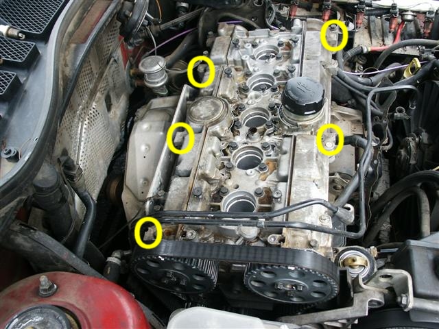
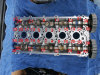
HURRAH!!! Time to remove the cam cover. It has 40 bolts and it's glued down with it's gasket making sealant (anaerobic sealant). It was suggested that the bolts be removed in a staggering pattern staring from the outside working in. I don't think it matters since the cover is glued down and has to be pried apart but I did it anyway. So I removed them in a staggering pattern. I broke all of them loose first (a half of a turn), once they were all loose I finished removing them. I loosened 2 on one end and 2 on the other end, matching screws and working my way in to the middle. When I started, I loosened all of them about 1/2 turn, all of the bolts in that pattern. Then went back and did another 1/2 turn. By then all of them were loose and I took them out.
NOTE: Screw removal for the cam cover bolts were done in reverse order. -
Once all of the bolts are out, find the taps and pry the cam cover off the head. Try to use pry points at a time. I used 2 ratchet extensions.
WARNING: DO NOT PRY ON ANY OTHER SECTION OF THE COVER. DO NOT BE TEMPTED TO SLIDE A SCREW DRIVER BETWEEN THE CRACKS ONCE IT STARTS OPENING TO GET IT OPEN FASTER. ONLY PRY THE SEPARATION TABS.
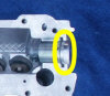
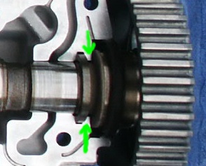
WARNING: When you separate the cam cover, watch the way you take it apart. You should only lift it straight up or hinge it front (grill) to back (windshield) or back (windshield) to front (grill). If you lift the cover off any other way, you will likely damage the cam lip lobe(s) in the cover or head (the cams have lips on the front end that sit in groves in the soft aluminum head. If you open the cover by lifting the rear seal area end up it will cause those lips to cut into the cover and chip/break the groves).


WARNING: Do not damage the head or cam cover when you separate them (by dropping the cover, prying between the surfaces or lifting the cover off on an angle).
WARNING: When you get the cam cover loose, pay attention as to where the cams are and what they are attached to. I made sure they were NOT stuck to the top but lying on the head. You don't want them to fall and get damaged. -
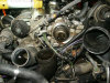
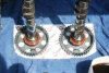
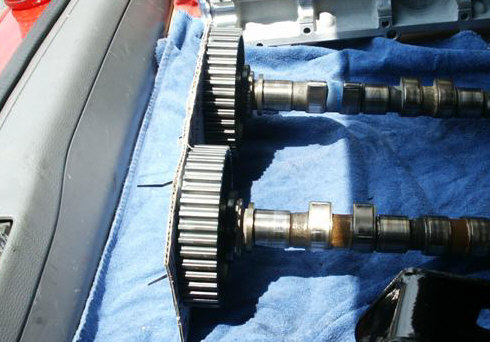
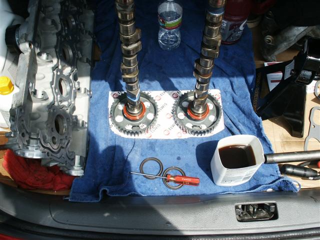
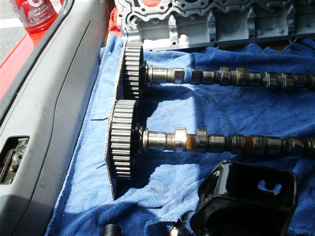
Remove the cams, with sprockets attached, and put them somewhere where they won't get damaged and will stay clean. If you did not lock them with a system like shown above, make sure you do not get them mixed up, exhaust and intake.
WARNING: Be careful when you lift them out of the head, not to damage the lobes. I think it would be safe to lift the sprocket ends out first, then the rear ends out.
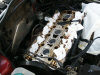
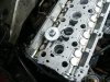
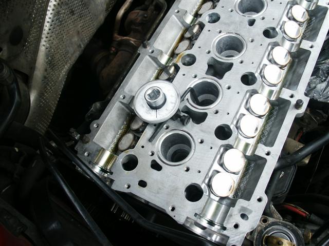
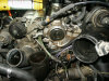
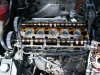
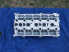
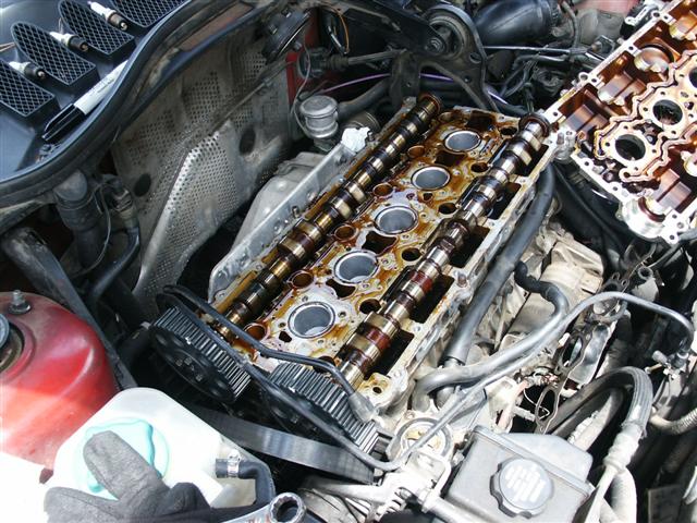
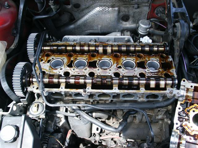
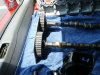
NOTE: You can now see the lifters, do not remove them yet. -
Remove the cam shaft seals if you have new ones to replace the old ones. Just slide them off the shafts. The front seals are larger than the rear seals so the front seals will slide all the way down the shafts. Again, do not remove or loosen the bolts that hold the cam sprockets on.
If you do have new seals, oil them up and slide them on the shafts. -
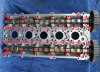
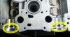
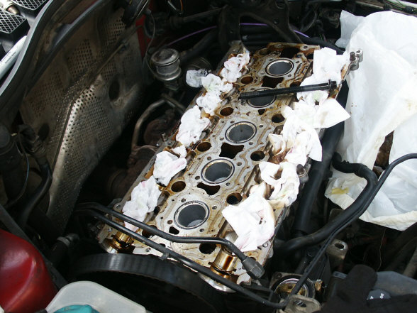
Remove the spark plug o-ring seals. There are 5 of them that seat in the groves around the spark plug holes.
-
Clean up a little bit of the oil, enough to get the top surface of the head clean and oil free.
-
Clean the top of the head with the Gasket Remover. If the surface does not come clean easily and you find the need to scrape it, I think it is best to start with a soft scrubber and work your way to something harder. I started with a soft plastic kitchen scrub pad and worked my way up to a dense plastic scrub pad, like the one you would use to scrub a pot. Tracy suggested that you use plastic charge cars cut up to the size you will need to scrape the surface you are trying to get clean. I found that the Gasket Remover softened stuff up enough to get all of the gasket off except in a couple small crevices. Then I used something harder to get those slots cleaned. NO METAL.

WARNING: Never use anything harder than the aluminum you are trying to clean, it will scratch is and likely cause a bad seal that will cause oil leaks.
NOTE: You may want to use a shop vac to get the scrub pad and gasket fragments off the head. -
Clean the cam cover (bottom side). Make sure these surfaces that mate will be clean, dry and lint free (spotless).
-
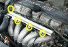
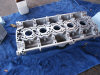
Once both surfaces are clean, remove the old lifters. You can get them out easy with a magnet. Once the lifters are out, you can see the top of the valves.
-
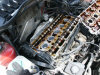
Install the oiled lifters into the head. Try not to get oil everywhere. They go in tight and at a certain angle. I had to tap half of them in. Tapping them with the handle end of a small screw driver. I tapped around the edges and middle of the lifters until I seen them falling in place.
-
After all of the lifters are in, clean the head mating surface one last time with Acetone. It will strip away any oils and dry very fast. You have to use a lint free cloth, I ended up using an old t-shirt.


RE-INSTALL PROCESS: When installing the cam cover, there are several ways to deal with the cams as mentioned in step 38 of removal.
-
Some lock the cams in the cover and use a special tool or a fabricated clamping tool to press the surfaces together, then they install the screws.
-
Another way is to lock the cams to the cover and put some normal type clamps on it and start installing the 40 screws down, which brings the surfaces together.
-
I chose to attach something to the front of the cam gears to prevent them from rotating, setting them in the head, then I set the cover on the head, used some squeeze clamps to keep the cover in place, then I used the screws to pull the cover down to the head.
-
Make sure you have oil or lube on the cam journals, lobes, head journals, lifter surfaces, etc., the cams path. Some people use oil some use a little grease.
-
Make one last pass at making sure the top of the head mating surface is clean, dry and lint free.
-
Clean the mating surface of the cam cover with acetone.

-
Lay the cam cover upside down on a clean surface and apply the anaerobic sealant. I used a small foam roller and small plastic roller pan. Make sure you get a thin level amount on all of the mating surface. The foam rollers I purchased had it's own rolling pan, I did not realize that and purchased another rolling pan (the green one).
_small.JPG)

WARNING: Do not apply to much of this sealant on the surface. There are a few small oil channels that you do not want to clog with the sealant.
NOTE: This stuff will not dry in the air so do not feel rushed. I left some in the roller pan and it was still wet 3 days later. It will dry once the surface is mated together and no air gets to it. -
Make sure you have the front cam seals in place.
-
Set the cams in the head if you have not done so already. The cams should be secured by the cam sprocket locking system you made.
-
Set the cam cover on top of the head. Make sure you have the cover aligned properly. Be careful not to damage the cam seals or the cam lubes. The surfaces will have a lot of gap between them.
-
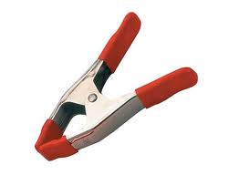
Install whatever type of clamping system that you have planned to use. I used 4 squeeze clamps like the ones pictured below. I positioned them at the corners of the cover, where the pry points are located.

-
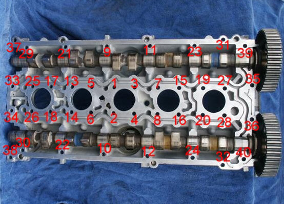
Set all 40 cam cover screws in their holes. In a special pattern, tighten the cam cover bolts. From the center, install the screws so they are snug, I say finger tight and 1/2 turn. The photo below will show you the pattern I used. Each pass I made, by the time I got to the end of the cover, the center screws were very loose again. So I again, made them finger tight plus a 1/2 turn. When I made it to the end and the center ones were still tight I did the final torque value which is 15 in lbs.
As I went from the center to the end, the center bolts were pretty loose the next round. I continued the pattern until the head was torqued. This process took about 15 minutes. While I was tightening the bolts the clamps were holding it down as much as they would.
WARNING: If you just start tightening bolts and not using the proper pattern, you will likely BREAK (snap) the cam. That's right, you can actually break a cam shaft in two. So, do not try to speed up this process. If you used a drawdown camping system, it would likely speed up this process.
The final torque value is IN LBS not ft lbs., if you torque them down by ft lbs you will break several of the screws. DON'T DO IT. -
Once the cam cover is secure, you can clean any sealant that came out of the edge, shouldn't be much if any.
-
Install the rear cam seals if you have not done it already.
-
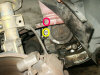
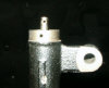
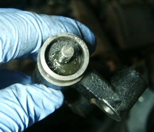
Using the large c-clamp, compress the timing belt hydraulic tensioner. You should use a half turn every few minutes between turns so you don't damage the tensioner. If it leaks any fluid out of the shaft area, it is bad and should be replaced.

-
Once the tensioner is compressed and pinned, install it and the rest of the timing belt as outlined in some timing belt instructions. I would suggest these: Timing Belt Instructions
Start at step 4 and skip any steps you do not need. -
From here, assemble the motor from step 36 working backwards.
.JPG)


FINISHING UP: Once you have it all back together, I would suggest that you check the oil level and start the car. There is a GOOD CHANCE that the lifters will be ticking. I actually heard the ticking lifters moving around in the head. It sounded like several of them were ticking when I first started the car. Remember, most of the oil was cleaned out of that area and new lifters will likely have to get oil pumped into them while they are being compressed by the valve springs and cam lubes. The ticking lifters went on for several minutes. I let the motor run for about 15 minutes before I turned the motor off. After that, I cleaned up the area and took the car for a drive to the store. I got on the freeway and by the time I was at the store just 3-1/2 miles away, the lifter noise was gone and has not returned.
CAM LOCKING INSTRUCTIONS: In case you did not lock the cams when you removed the cover, this is how I did it post cover removal.
-
Set the cams on a clean surface.

-
Set the cam cover on the cams.
_small.JPG)
-
Set the top of the timing belt cover where it goes on the cam cover.
-
Align the cams so the marks line up to the cover.

-
Cut a stiff piece of cardboard the width and height of the pair of cams.
-
Set the timing belt cover aside so that you can work with the cam sprockets.
-
Press the cardboard on the front of the cams to make impressions of the cam sprocket bolts.
-
Put holes in the cardboard so that the sprocket bolts fit in the holes.
-
Set the cardboard on the front of the cam sprockets as they were aligned properly.
-
Put holes in the cardboard in at least 2 position so you can zip tie the cam sprockets to the cardboard, which would prevent the cams from turning while the cam cover is being drawn down.


.JPG)

Please leave a donation, see the bottom of this page.
End of instructions.