Toshiba Satellite L355 Assembly Instructions
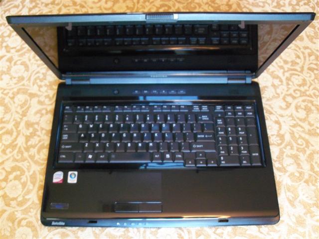
These instructions will guide you through the assembly process of the 17" Toshiba Satellite L355 laptop computer. I had to crack the case of one because the power adapter connector had broken off inside of the computer base which means the plug end had fallen into the computer. The good thing about this laptop is that the base is so large (being a 17" screen model) that the power connector is NOT mounted on the mother board. This means that you can easily fix the problem on this machine vs so many other laptops where the mother board would need to be replaced or the connector would need to be replaced on the mother board (a tough solider job). It took me about 2 hours to complete the entire job but you should be able to do it quicker with these instructions. These instructions can be used for replacing a number of parts on this computer. From the monitor assembly, keyboard, or entire mother board.
Tools Needed:
| Small cross tip screw driver | Small flat tip screw driver |
| Very small cross tip screw driver | Very small flat tip screw driver |
| Glue gun for craft work | Standard paper clip |
| Parts layout sheet | Super glue |
Instructions: Read each step in it's entirety before doing the procedure. It will help you avoid breaking parts, harming yourself, etc.
NOTE: If you only need to replace the keyboard, go to step 12 and complete it and step 13.
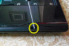
- With power on the computer, eject the CD drive door. If power is not on, you can manually do this at step 6. If you do not have power, will need a paper clip or some other narrow object to push in the "manual eject hole".
- Turn off the computer. Start - Shut Down.
- Unplug the computer.
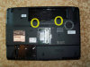
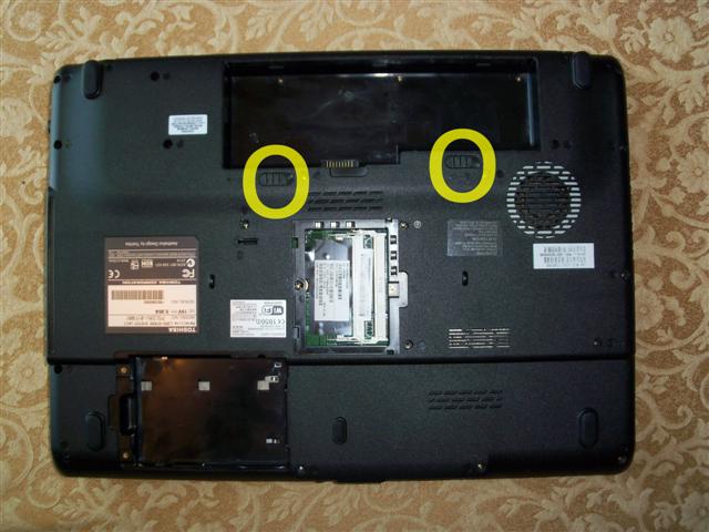
- Flip the computer over and remove the battery. It has 2 latches,
an un-lock latch, then the release latch.
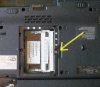
- Remove the panel that covers the RAM, then remove the RAM chips.
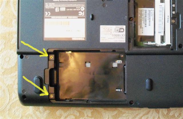
- Remove the panel that covers the hard drive, then remove the
hard drive.

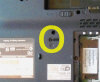
- Remove the screw that holds the CD drive in, and remove the
drive. It will pull out once the screw is removed.
- Remove all of the F7 screws, I believe there are 19 of them. It would be best to set them on the "parts layout sheet".
- Remove the 3 screws from the battery area.
- Remove the 2 screws from the back of the computer near the
hinges.

- Flip the computer over and open it.
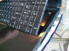
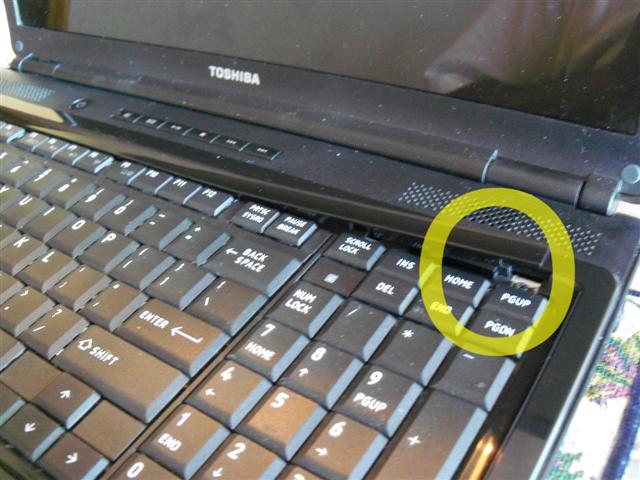
- Remove the trim piece from the rear edge of the keyboard. It
covers the keyboard screws. I used the flat tip screw driver and
pried into the edge near the right side and lifted up on it until it
started to rise. Once it started to come up, it released pretty
easy.

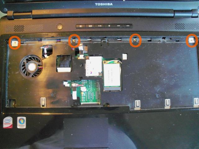
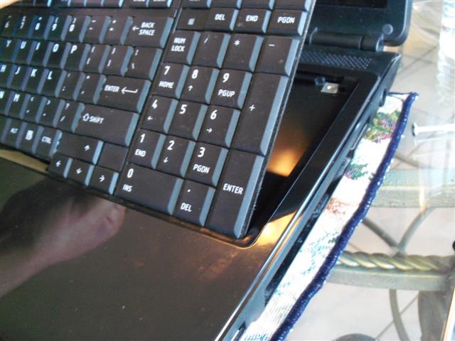
- Remove the keyboard. You will need to remove the 4 screws at the
back end, release the center clip at the F9 key, lift up on the rear
edge, then lift the keyboard towards the display until the front
clips free themselves. Once the front clips are free, release the
cable ribbon from the mother board and remove the keyboard from the
computer base.
CAUTION: The keyboard is connected to the mother board by a wire connection ribbon. Be careful to release the latches on the ribbon ends before you try to remove the keyboard from the computer base. Failure to do so may damage the keyboard, mother board, etc.

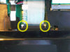
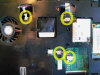
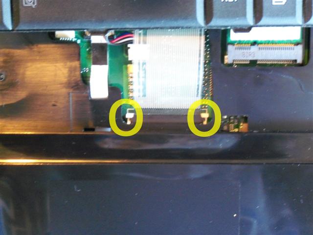
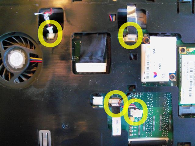
- Release 4 other connectors that are attached to the base top and
mother board. Power connector, Speaker wires, Touch pad controls,
and Media buttons. I used the small tip screw driver to release the
cables. They are orange on the parts layout sheet.
CAUTION: Failure to remove these connectors will likely damage the fragile wires that connect these components. Be careful to release the ribbon clips before removing the ribbons and use care when unplugging the other 2 connections.
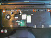
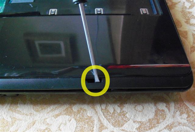
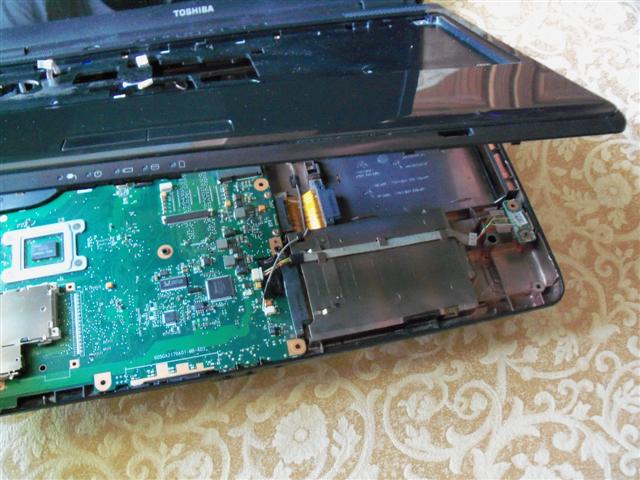
- Take the top of the base apart from the bottom of the base. I
used the small size flat tip screw driver to pry out on the right
display latch hole to get the base apart. Once it cracked apart, I
slid the other screw driver in the opening and then worked around
the base to separate it. It has clips around it and came apart
pretty easy.
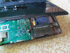
NOTE: Once you separate the base, the rest is pretty visual. You can see just about anything else you need to do.
* To repair the plug outlet, go to step 16.
* To replace the mother board, go to step 19.
* To replace the monitor, go to step 22. - On the machine I had, the actual plug receptacle end was chipped/broken and this allowed the receptacle to fall into the base. So I found the pieces and glued them together with super glue.
- Spread a little hot glue in the bottom of the computer base
where the plug receptacle slides in the slot.
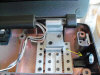
- Before the glue dries, press the receptacle into it's slot and
hold it there for 60 seconds.
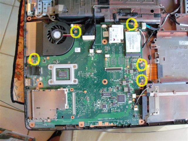
NOTE: To reassemble the computer in reverse order from step 15. - To remove the mother board, unplug the wires that connect to it.
Monitor, monitor back light, web cam, wi-fi antenna, etc.
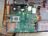
- Remove the 5 screws that connect it to the bottom of the base.

- Push in the PC slot release button and work the mother board off
of the computer base.
CAUTION: I actually did not remove the mother board from the base so be careful not to break anything in case I forgot to list something.
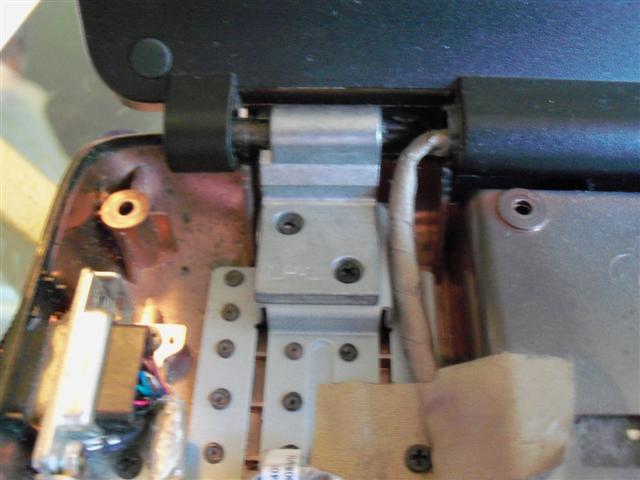
NOTE: To reassemble the computer, reverse steps 21 through 19, then steps 15 through 1. - The monitor is held in place by the hinges. There are also cables and wires that connect it to the mother board. Unplug all of the monitor wires, cable, back light wires, wi-fi wire, web cam wire, etc.
- Unscrew the hinge screws, 2 on each side, 4 total.


- Lift the monitor from the base.
NOTE: To reassemble the computer, reverse steps 24 through 22, then steps 15 through 1.


Please leave a tip, see the bottom of this page.
End of instructions.