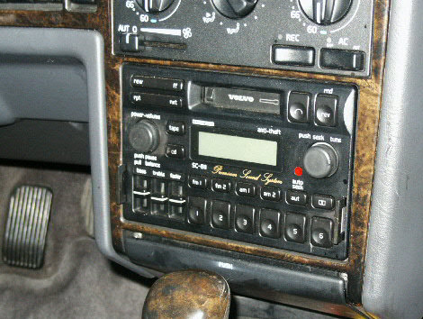
Radio mp3 Modification for the Volvo SC-813, SC-815 and SC-816 Car Stereo
After reading about the tape deck adapter bypass mod to get better sound from the stereo with a headphone to mp3 player cord, I just couldn't resist any longer. So I read several threads on www.MatthewsVolvoSite.com and dove in. I tend to go a little overboard so I decided to make a plug in and the best I could come up with was putting a plug in one of the switch blanks. That way I won't need a long run if I decide to put my mp3 player (phone) in the GPS mount near the drivers side window. The mod can be done in 1 hour or less. (Link 1 - Link 2)
I have used the Phillips cassette adapter with satisfaction. The adapter is quiet and the sound quality has always been good, even when playing music on my old Treo phone (as the mp3 player). With the mod the sound is a little cleaner and it also has deeper bass response. The method I use will leave the tape deck operable. Some people stick some kinda of tape in there and cut the power lead to the motor so the deck doesn't kick the blank dummy tape out but why disconnect something that works?
I do have one issue with my droid... It likes to cut off sound to the head phone jack when it doesn't sense a signal from the player, if there is a 5 second or more pause in the sound. This happens when Pandora is searching for another song to play. Once the next song is found the droid kicks the sound back to the jack. When this switch happens, I hear a thump in the stereo speakers, almost sounds like I pulled the plug and plugged it back in. Your call, not sold on it but it is nice to have the option.
Tools Needed:
| Ohm Meter | Drill |
| Electrical Tape | 1/4" Drill Bit |
| Solder Iron | Solder |
| Straight Edge Razor | Shielded Audio Cord (3 wires) |
| Phillips Screw Driver (cross tip - magnetized works better) | Good Scissors |
| 2 Small Zip Ties | 1/8" (3.5 mm) Female Audio Jack (I got it from Radio Shack, P/N: 274-0249, cost was about $3.50) |
| Metal File | Needle Nose Pliers |
| Dash Switch Blank |
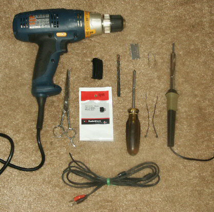
(Most of the tools)
NOTE: While doing this mod, it might be a good idea to replace any burned out light bulbs in the radio. Click Here
Instructions:
-
Get the radio code. It's a 4 digit code that you will need to turn the radio back on once you install the radio.
-
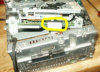
Remove the radio from the dash. Push in on the quick-release tabs in both sides of the radio and pull it out.
NOTE: If you have a good grain shifter knob, you may want to put a cloth or something on the shifter knob to avoid scratching it up with the bottom of the radio.


-
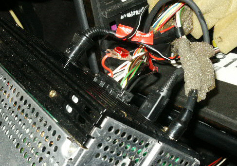
Unplug the wires on the back of the radio to completely remove it from the car. There are usually 2 wire harnesses, maybe a cd changer plug, maybe a power amp plug and 1 or 2 antenna wires.
-
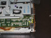
With the radio out, remove the 2 screws from the top to gain access to the inside of the radio. Once the screws are out, lift the top off from the rear and pull the front back away from the faceplate, there are 3 tabs in the front edge that slide under the front of the stereo.
NOTE: Now would be a good time to replace any bad bulbs you have in the stereo. -
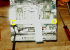
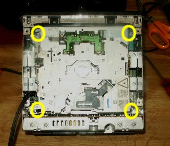
If you have a CD player in the stereo, remove the 4 screws that hold it in the unit (if you do not have a CD player, skip to step 7). Once the screws are out, lift the unit up enough to unplug the ribbon. The ribbon does not have a release, it just pulls out. Once the ribbon is unplugged, set the CD player aside. On the SC-816 the 2 front end screws were in holes in the CD unit and the rear screws were on the outer edges.

NOTE: Leave the ribbon plugged into the lower board. -
Remove the bar that separates the CD player from the tape player. It has 2 screws in it.
NOTE: There are 2 options for connecting the wires to the tape deck module. One is the top circuit board, the other is the rear circuit board. I used the rear board for the SC-813 and SC-815 but that option did not work for the SC-816. On the SC-816 I had to use the top circuit board for the mod to work. You may be able to use the top board for all of the decks. I will post pics of both. However, if you plan to use the top board, you do NOT have to remove the tape deck module from the head unit, I did for easy access.
NOTE: The differences between the top and rear control boards:
REAR: When I used the rear circuit board I had NO sound distortion and the sound volume on my mp3 player was level with the rest of the system when set to about 80% loudness.
TOP: On the SC-816, I had to use the top circuit board. There was sound distortion when I had the mp3 player turned up. The sound quality and system balance was best when the player was turned up to around 40% loudness.
-
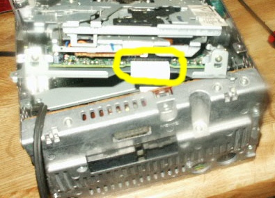
Unplug the ribbon that connects to the radio module to the board. I unplugged it at the top of the tape module. Again, leave the ribbon connected to the lower control board.

-
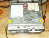
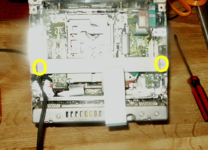
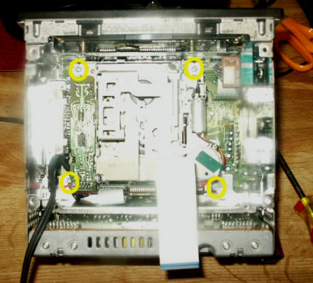
Remove the tape deck module from the head unit. There are 4 screws on the corners. Once the screws are out it will lift out.

-
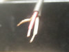
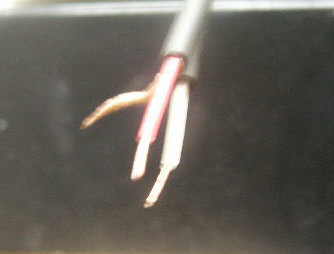
Prepare your wires to be connected to the board. If you use a stereo cable like I did, strip a very small amount of the wire insulation of the red and white, then connect both of the shield, ground wire together. Leave a little more bare wire on the end that connects to the 3.5mm plug (leave a lot more ground to work with).
-
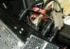
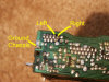
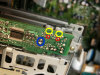
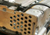
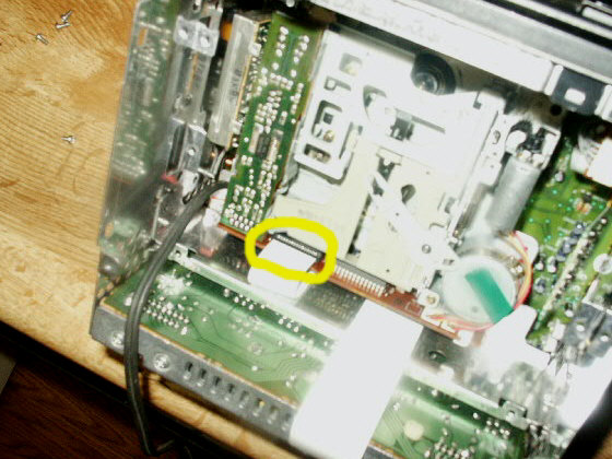
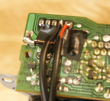
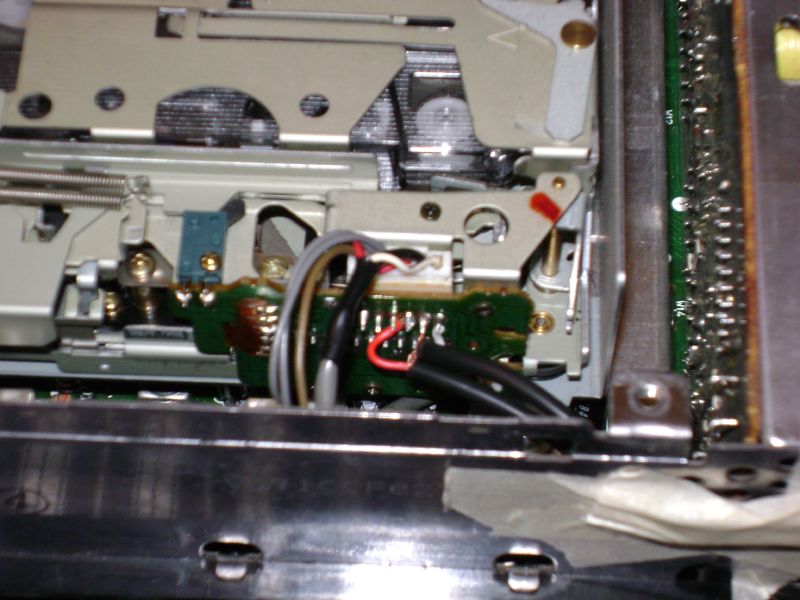
A) THE REAR BOARD (I prefer this method): Solder the wires to the 4th (left/white) and 5th (right/red) wires from the top left corner. You can pin out a ground with the ohm meter. Check for a high ohm reading when you pin the joints to the chassis. You can also ground the wire to the chassis.

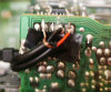
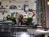
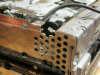
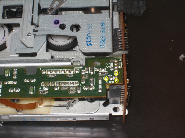
B) THE TOP BOARD: If you look towards the front of the tape module, you can see the markings for the left and right channels. Then you should pin out the ground with the ohm meter or ground it to a chassis. The yellow is the label, the red is the actual left and right joints to solder to and the blue shows points that may be the ground (the top one was the ground for me but in another users photo the lower pin was the ground - you really need to ohm it out to the chassis to be sure).
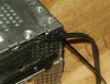
C) ON THE SC-710 AND SC-715 DECKS: Here are pictures of a solder location on the older decks. If you have one of these decks, I encourage you to replace them with a deck that has the words "Premium Sound System" on it. The sound is 20 times better with the extra power.
-
Once you have the wires soldered to the board, secure the wire to the tape deck chassis with a small zip tie so it does not stress the wire solders on the board.
-
Install the tape module into the head unit and connect the ribbon. The ribbon pushes in but be careful not to damage it. This is when your magnetized screw drive tip comes in handy, 4 screws.
NOTE: It would be a good idea to run the unit out to the car and test it to be sure it works properly.
- The stereo will work without the CD unit installed.
- Hook the deck up and slide the cassette adapter tape in the deck and connect your mp3 player to your cord.
- If you are going to use the 3.5mm plug like I did you will need to connect it, see step 15.
- If the unit works, proceed with the following steps, if not make sure your connections are clean and you do not have a wire lying on another solder point. If you can not get it to work from the solder board you used, try the other board.
-
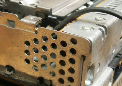
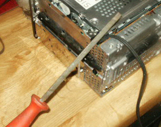
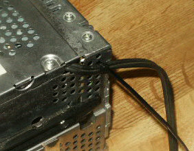
Remove a notch from the head unit from with the file and pliers so the cable will not be crimped with them running through it. Zip tie the wires to head unit to secure them.

-
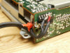
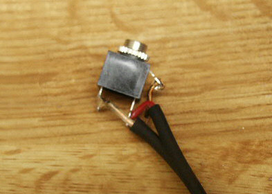
Connect the other end of the wires to the 3.5mm adapter. The ground points away from the jack, the right/red is closest to the ground, and the other is the left/white.
NOTE: If you would rather have the head phone male tip on this end of the cable just use the kind of wire that has it and leave it attached. -
Install the support that separates the CD module from the cassette module.
-
Connect the ribbon for the CD module and install it, 4 screws.
-
Put the lid on the head unit, 2 screws.
-
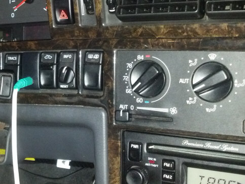
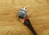
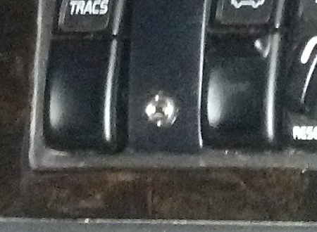
Drill the 1/4" hole in the switch blank. I put the hole in the lower end of the blank and not the middle because the blank is designed to hold a plug in it if need be and the bracket for the plug was in the way. I suggest removing the blank from the car before drilling a hole in it. You can get the blank out by removing a switch next to it then push the blank out from the back with your finger.

-
Take the head unit back to the car to install it.
-
Feed the new head phone jack wire to where you want it to be.
-
If you are using the 3.5mm jack, route the wire to that part of the dash then connect the jack to the blank. (I believe you can install more than 1 jack in different locations if you want. They should chain together fine. I considered putting one at the back seat ash tray on the back side of the center console, one in the center console under the ash tray, etc.)
-
Snap the blank into place and finish installing the radio.


Please leave a donation, see the bottom of this page.
End of instructions.