Assembly Instructions For The WinBook T200 / ECS - Elite G410 Laptop Computer
These instructions will guide you through several aspects of replacing parts on the WinBook T200 or ECS / Elite G410 laptop computer.
I have the WinBook version of the computer, kinda wish I had the ECS version. From what I know, some of them have a built-in webcam and a built-in TV tuner. Anyway, my display started flickering and I finally figured out that the ac jack soldered on the mother board was worn out and broke internally. So after several months of holding the cord just right and keeping an upward pressure on it, I decided to get aggressive in hunting down the receptacle before I caused the mother board to catch fire or it totally break leaving me stuck without my computer.
I had NO success finding anyone that admitted to having the
receptacle I needed so I took the computer apart and took a good look at
it. A lot of computers produced during the same time frame shared parts
like this so once I had a good look at it, I searched several computer
jacks of computers that were built during the same times. I came up with
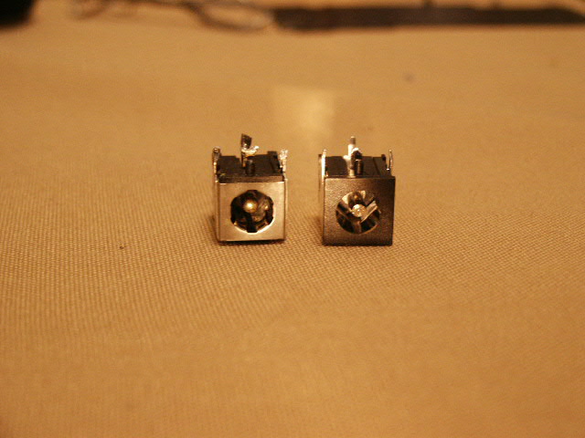
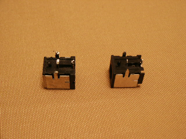
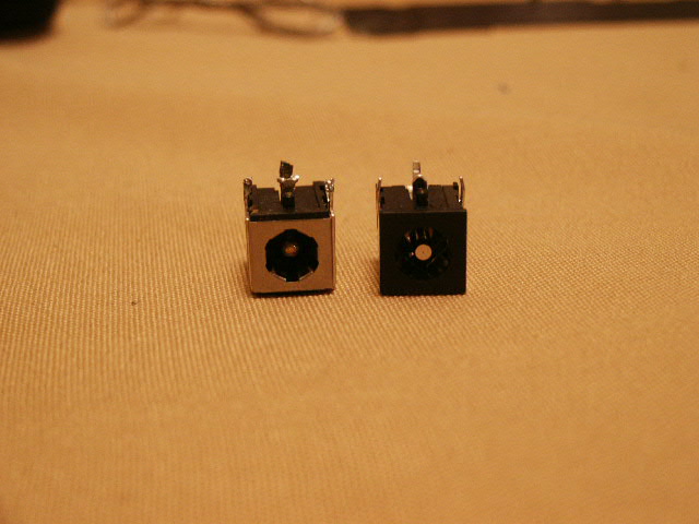
a couple. The WinBook 331 and Mitac 8060B. The WinBook 331 power jack
photo looked identical. However, when it arrived it had less tension
springs inside of it (has 4 instead of 6), but it still works perfectly.
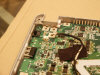
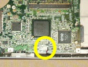
So do a search and find one that looks like this photo. It has 3 prongs
across and one in the back. They also have a post up front to help keep it
straight in the mother board.
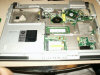
This computer really is a pain to get to this part. It has a 2 part mother board, one of which has to be taken totally out.
You will need the following:
- AC - DC Power Jack Receptacle.
- Small standard tip screw driver.
- Small cross tip screw driver.
- Soldier
- Soldier iron.
- Screw layout sheet.
Instructions:
- Shut down the computer.
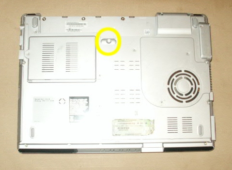
- Turn the computer over.
- Remove the battery. Release the latch and pull the battery out.

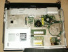
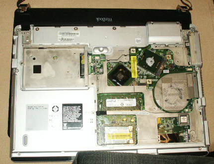
- Remove the bottom access panel. Blue stuff, 7 screws. Once you
have all of the screws out you can pull the panel off by starting at
the edge where the battery meets it.
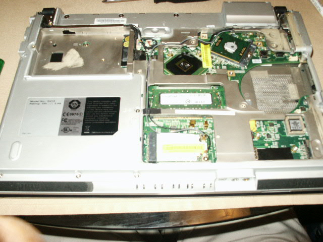
- Remove the hard drive. It will simply slide out.
- Remove the monitor. Unplug the cables and remove the hinge
screws. Green screws 3 on each side. Then lift the monitor away from
the base.
- Remove the keyboard screw from the mother board (red).
- Remove the screw that holds the cd drive in (orange) and remove the cd drive.
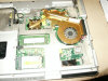
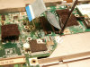
- Remove the heat sink. Loosen the screws (7), unplug the fan
connector, and lift it away from the base.
- Remove the rest of the base screws (15 - black).
- Flip the computer over.
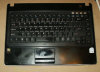
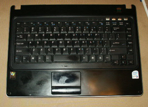
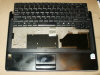
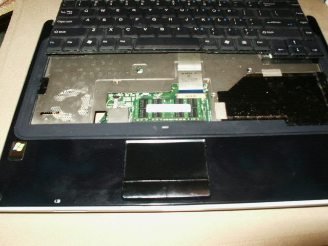
- Remove the keyboard. Release the tab on the left side (1) and
pry a small screw driver under it. Then work your way around the
front edge near the space bar releasing those tabs (5) and around to
the right side (1). Once the tabs are released, lift the keyboard up
and rest in near the monitor edge. Remove the 2 screws from the
panel under the keyboard, lift the panel away and release the ribbon
cable for the keyboard.

- Release the mouse ribbon.
- Release the mic wire connection.
- Remove the 4 screws from under the keyboard.
- Separate the base halves. Work the top of the base from the
bottom.
- Unplug the speaker cable from the mother board.

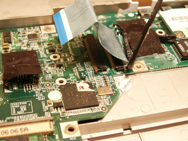
- Release the mother board bridge cable (I undid the left side).
- Unplug the modem cable that stretches across the mother board.
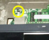
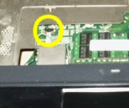
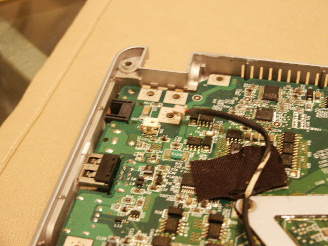
- Remove the screw that secures the mother board to the lower
base, it's near the battery connection.
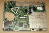
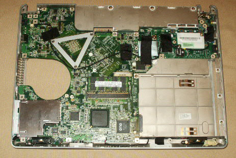
- Lift the mother board from the base.
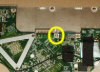
- Carefully release the solider from the receptacle on the mother board.
- Carefully solider the new receptacle on the mother board.
- Reverse the disassemble instructions.


Please leave a tip, see the bottom of this page.
End of instructions.